Hi-MedFER "NC" Beacon
1704.983 KHz
This beacon is operated per FCC Part 15 rules with a maximum input power of 0.1 watt and a maximum antenna length of 3 meters.
This beacon was placed on the air on 8 January 2004. At that time it was sending a square wave pattern with approximately a 30 second period and a 1 Hz shift. Within the first few hours of operation confirmed reception reports were received from the following radio operators:
|
08 Jan 2004 |
John Andrews | Holden, Massachusetts | 670 miles |
| 08 Jan 2004 | Jay Rusgrove | Burlington, Connecticut | 603 miles |
| 08 Jan 2004 | Mitch Powell | London, Ontario | 537 miles |
| 08 Jan 2004 | Dale Parfitt | Glenville, North Carolina | 160 miles |
| 08 Jan 2004 | Larry Putman | Pasadena, Maryland | 339 miles |
| 08 Jan 2004 | Lloyd Chastant | Marriottsville, Maryland | 337 miles |
| 08 Jan 2004 | Bob Riese | York, Pennsylvania | 380 miles |
| 08 Jan 2004 | Mike Staines | New Berlin, New York | 576 miles |
| 08 Jan 2004 | Roger Thompson | Smithville, Mississippi | 463 miles |
| 21 Jan 2004 | Denis Cote | Swansea, Massachusetts | 658 miles |
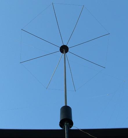
Hi-Medfer NC Antenna
The antenna vertical mast is a 9 foot section from a broken swimming pool brush pole. It is about 1.5 inches in diameter and strong for it's weight. The top hat hub is made of marine plywood. The top hat elements are from a salvaged TV antenna and are approximately 30 inches long per element. A 14 gauge aluminum wire forms the top hat perimeter.
Hi-Medfer NC Loading Coil
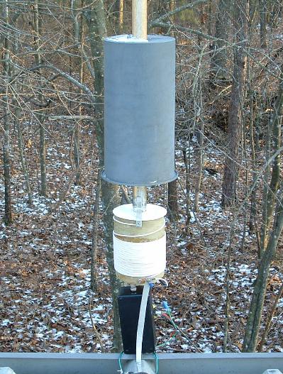
The loading coil, shown here with the cover lifted, is wound with No. 14 insulated wire removed form Romex type cable. The coil cover is a concrete pour test container. The coil form is thin wall fiberglass pipe which was scrap from standby generator fuel line containment project. The form top plate and inside centering spacer was cut from a plastic bucket. Unseen in this view is the insulator which joins the radiating element to the support pipe below the roof line. The insulator is a fiberglass tube from a damaged VHF antenna. The black box contains the complete transmitter. A strip of aluminum connects the coil ground to the metal roof of the building.
Measuring Antenna Current
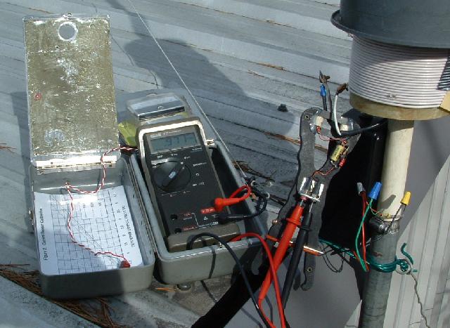
Antenna current being measured with current probe designed by Lyle, KØLR. This measurement was made with output amplifier running 0.1 watt input power (2.5 volts at 0.040 amp). The meter voltage of 0.971 volt translates to approximately 0.098 amp of antenna current.
Hi-Medfer NC Transmitter
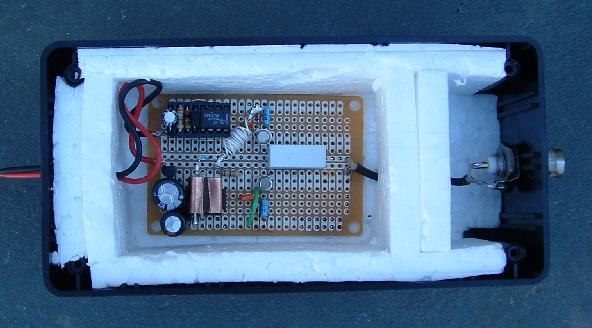
The basic transmitter design is from Lyle Koehler's, KØLR, web page. The exciter is a simple Epson oscillator chip which is located under the copper tab. The copper tab has a 600 ohm resistor inside which is heated allowing slight frequency shift of the oscillator. At the upper left of the board is a 555 timer which powers the oscillator heater providing an easily noticable wave form when displayed with Argo or Spectran type software courtesy of Alberto, I2PHD.