W4DEX LOW FREQUENCY PAGE
(Weak-signal Operation on Low Frequency by Stewart Nelson, KK7KA)
The first known WOLF mode two way contact was made by this station, "NC", and John Andrews' "TAG" in Holden, MA on 11 Jan 2004
LF Beacon "NC" is located near Stanfield, North Carolina, Grid EM95tg The beacon is operated in compliance with the Federal Communications Commission Part 15 rules. These rules specify a maximum DC power input to the final amplifier to be 1 watt and a maximum antenna length to be 15 meters.
Reception Reports Received - Winter 2004 - 2005
Reception Reports Received - Winter 2003 - 2004
Reception Reports Received - Winter 2002 - 2003
DDH47 Special Transmission 09 Nov 2002
Best DX Reception for this beacon was made by Steve McDonald, VE7SL, MAYNE ISLAND, BC CANADA Mode QRSS120 Path 2360 miles (3798 km) Date 4 January 2002
Click the link below for the VE7SL Radio Notebook
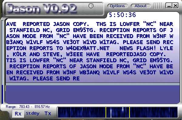 Best DX for this beacon in JASON mode made
by Lyle Koehler, KØLR, AITKIN, MN 1035 miles (1666 km)
on 2 February 2002
Best DX for this beacon in JASON mode made
by Lyle Koehler, KØLR, AITKIN, MN 1035 miles (1666 km)
on 2 February 2002
^^^^^^^^^^^ Click on above thumbnail to see Lyle's excellent JASON copy !
KØLR web site. Lots of good LF information
Click here for more JASON screen shots
NC Beacon Details
Beacon "NC" Antenna Loading Coil
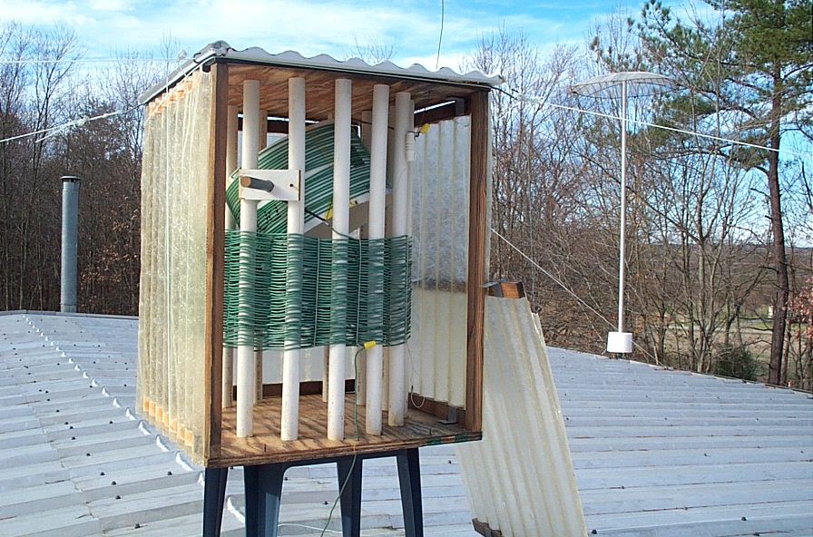
The beacon's current loading coil was built and put to use in 1996. Many changes have been made since it's inauguration and it's still evolving. The variometer was added in the fall of 2000. The coil base and top plates are 5/8 inch exterior plywood 24" by 24". The basket weave spacers are made of 15 sticks of 1" ID SCH40 PVC pipe about 30" long. Holes were drilled into the top and bottom plywood plates to secure the PVC pipes. The bottom plate holes were cut for a tight fit requiring the PVC pipes to be beveled so they could be driven in tightly. The holes in the top plate were reamed allowing the plate to be easily removed. The top plate is secured to the four 1" square wood corner post. The outside diameter of coil form is about 20 inches. The coil wire is #12 solid, plastic covered. Presently there is 70+ turns on the main form. The turns count has changed several times because of antenna changes. The variometer coil form was cut from a 5 gallon plastic bucket and is wound with about 30 turns of the same #12 wire. The axle is a broom stick which replaced the original golf club shaft that I thought was fiberglass. I found it to contain graphite which caused severe detuning when it was touched to adjustment. The original coil had about 2.5 mh of inductance but I haven't measured the present configuration. Operating with the present antenna the coil will tune from about 165 to 180 kHz with the variometer not exceeding 90 degrees. If the variometer coil is tuned to bucking inductance position it will tune well above 190 kHz. The coil sits on a plastic stool on top of a metal building. The weather shields are cut from thin corrugated fiberglass panels glued to corrugated cut slats with silicon rubber. The panels are held in place with pins through the top and bottom plates and are easily removed. The antenna wire is feed through a Teflon tube which is passes through the top plate and the fiberglass panel that forms the roof. The contraption is guyed to the four corners of the building with weed eater line..
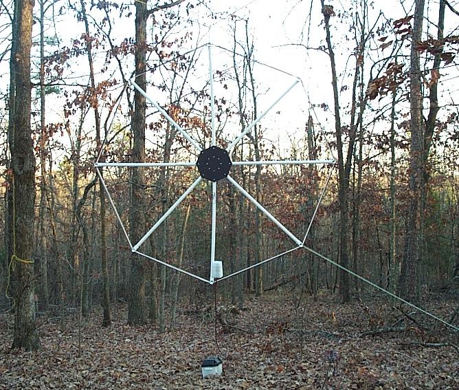
Beacon "NC" Antenna
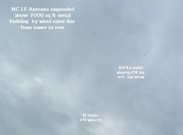
The antenna is a single #14 solid copper wire approximately 45 feet in length. Not the best for the job but cheap if you buy 14/2 with ground house wire and strip the wires from the sheath. The vertical wire extending from the coil to a support line (weed eater line) tied from a tower to a tree. At the top of this wire there are six 25 foot long drooping top hat wires. These wires are tied to the building corners with......you guessed it....., weed eater line. This picture was taken from the ground looking up. The dark spots are light weight plastic insulators. I have found most weed eater line to be a good high voltage RF insulator but not all of it is.
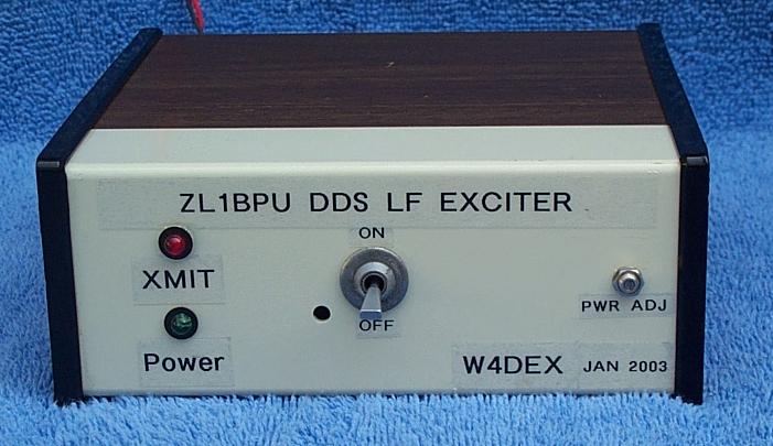
Beacon "NC" Transmitter
Many different signal sources have been used for the beacon exciter. The first was a late 60's vintage International Crystal OX-1 oscillator board with a crystal on 189.100 KHz. Later I acquired several selective level meters which have tracking generator outputs. This worked well but running a elaborate test instrument just for a signal source was a waste of power. After Lyle, KØLR, built and reported on the performance of the ZL1BPU DDS exciter I decided to build one. It's a great design!
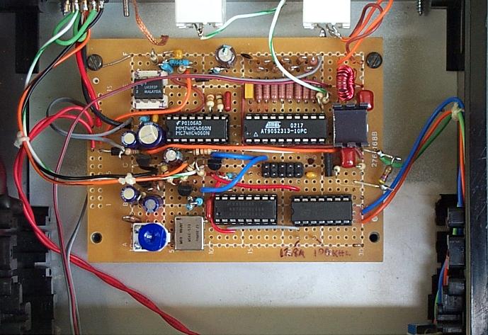
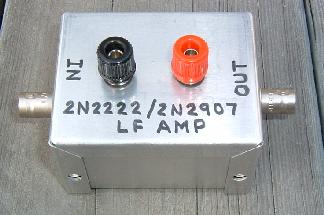
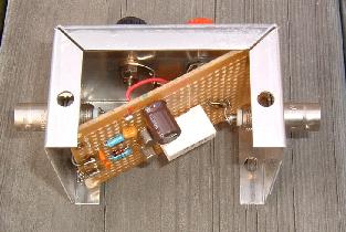
Beacon "NC" 1 watt Amplifier
The beacon final amplifier design is from the amp section of KØLR's "Simple LowFER Transmitter" circuit. It's very efficient and the parts are cheap. All the components here are recycled form junked circuit boards.
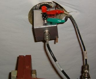
Below is the final amplifier inside the building. It is connected to a porcelain feed through insulator installed directly under the roof mounted loading coil.
Receiving Antenna
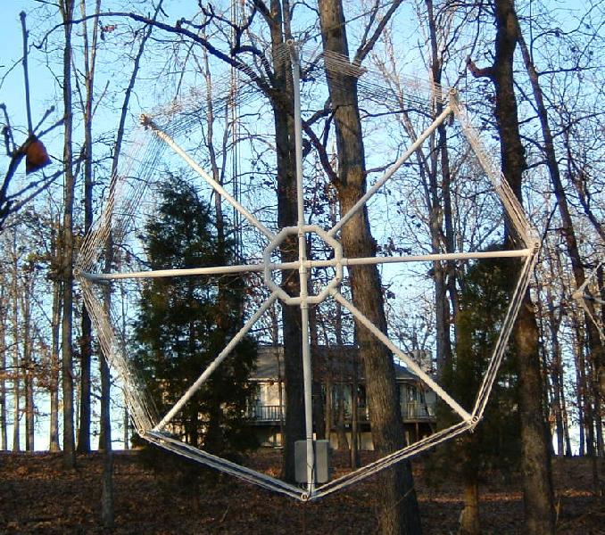
"Octalux" LF Receiving Loop
This loop has proven to be the best LF receiving antenna I have ever had. It is shown here hanging by a rope and with a Tupperware box as a temporary preamp cover. (Been temporary now for over a year :) The spokes are 1 1/4 inch ID SCH40 PVC pipe each 5 feet in length. The hub is constructed from two 5/8 inch exterior plywood plates bolted together with 1/4 inch bolts. The spoke ends are PVC Ts that have 20 evenly spaced slots for the wires. The slots were cut with a small diameter round file. The windings consists of 20 turns of #14 solid, insulated wire removed from Romex type 14/2 with ground. ($12 for 750 feet of #14 cu is hard to beat). The loop is center tapped and feeds a KØLR design balanced preamp. Presently it will tune from 95 to 200 kHz with the preamp tuning control. Adding a few hundred pf allows a range of 65 to 85 kHz. My goal was to cover the 73 to 190 kHz for the European ham bands and the 160 to 190 kHz Lowfer range with only the preamp control. I think I can still achieve this with a little tweaking. I've built many receive loops over the years but I just recently discovered what most LF loopers know and have been telling me. Balanced loops are great performers.
VLF Loop
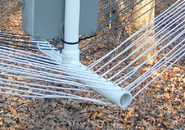
The frame for this loop is constructed entirely with 1 inch PVC. The diameter It is approximately 8 feet. The coil is wound with approximately 700 feet of #14 insulated solid cu wire removed from standard Romex cable. There are two separate windings, one on each side the spoke. Each winding consists of two layers, 14 turns spaced about 1 inch. With the windings connected in series the total inductance is about 3.2 mH which tunes well from less than 10 kHz up to 200 kHz.
Coil Construction Ideas
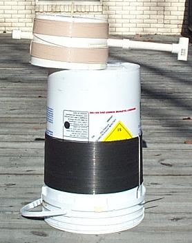 Bucket Variometer
This is an easy to build coil with variometer. Plastic buckets, PVC pipe mixed with a little wire.
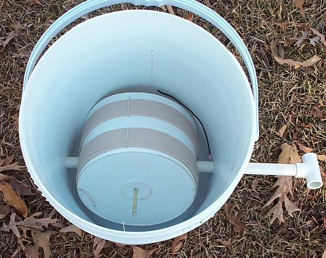
Interior view of above coil with variometer coil in place.
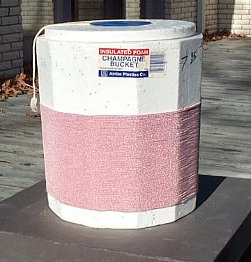 Styrofoam Coil Form
This low loss coil form is a Styrofoam champagne ice bucket.
LF Awards
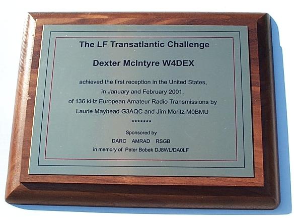
Award for first transatlantic reception of an amateur 136 KHz signal by a US station.
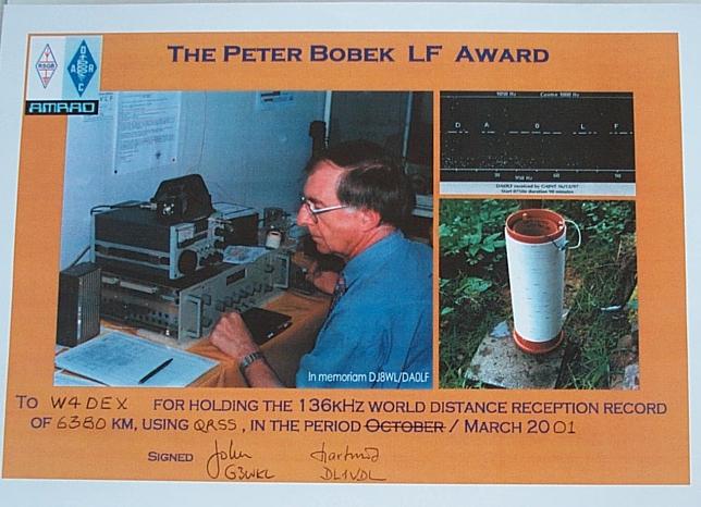
Award for best DX reception of an amateur station on 136 KHz.

Award for 1st Reception of New Zealand amateurs on long wave (136 KHz).