WD2XKO
Experimental Radio Transmitting Station
Stanfield, North Carolina, USA Grid EM95tg
Licensed under FCC Part 5 Rules
View Reception Reports View Station Log
License WD2XKO was issued on 25 May 2005 for experimental operation by the FCC in the LF spectrum between 135.7 to 137.8 KHz. The purpose of this experimental operation is study the effectiveness of new digital modes on LF with low ERP from small antennas. Hopefully this will provide some positive results and information which may be useful in determining the future of a possible US amateur assignment at 2200 meters. Amateurs in many countries already have privileges in this spectrum. Canadian amateurs have been permitted temporary experimental authorization at 2200 meters by individual request station request. See the VE7SL web page for more information.
This station commenced operation on the 4th of July 2005. The operating log can be viewed online and is uploaded each time an entry is made. View Log
Other Part 5 stations licensed for operation on 2200 meters with links to their web page if applicable:
WD2XES Holden Massachusetts
WE2XPQ Wasilla Alaska, ex WD2XDW Bartlesville, Oklahoma
WD2XFX Glenpool, Oklahoma
WD2XGJ Wayland, Massachusetts
Canadian Amateurs on 2200 meters include:
VO1NA Torbay, Newfoundland
VE3OT London, Ontario
VE7SL Mayne Island, British Columbia
VE7TIL Vancouver, British Columbia
Several LF operators are running near real time plots of QRSS mode North American 2200 meter signals. An explanation
of QRSS and other modes used on LF can be found on the W1TAG web site. Presently known running sites running
monitoring pages are:
W3EEE Mount Gretna, Pennsylvania (Click on Part5 for the latest window)
Steve also runs a window which monitors DCF39, a LF transmitter from Germany.
This has proven to be a valuable tool for determining trans Atlantic low frequency propagation
And a LowFer watering hole window centered on 185.300 KHz can be found on his page.
KI0LE Duluth, Minnesota
CT1DRP Portugal
DF6NM Germany
WD2XKO Equipment Information
Transmitter / Power Amplifier
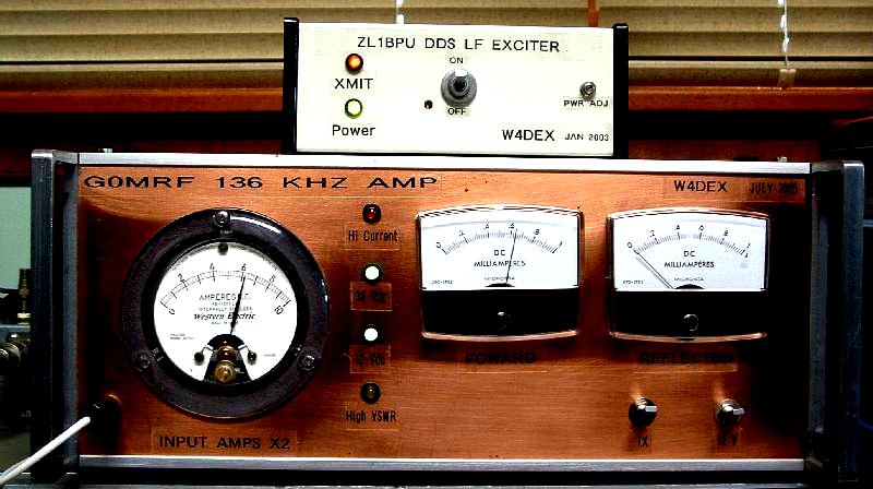
The present transmitter is a ZL1BPU DDS Exciter driving a G0MRF 300 watt amplifier. The amplifier has been modified with the M0BMU output circuit. With this modification the amp can be pushed to 500 watts for intermittent operation. While operating high duty cycle slow speed CW (QRSS) the amp performs well at 400 watts output.
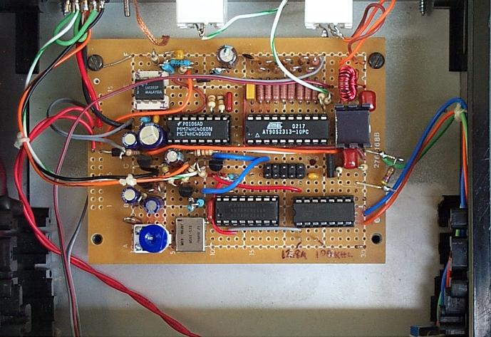
The DDS Exciter designed by Murray Greenman, ZL1BPU. For info see Murray's Projects page at:
http://sharon.esrac.ele.tue.nl/mirrors/zl1bpu/
Additional info by Lyle Koehler, K0LR, used for this project can be seen at:
http://www.qsl.net/k0lr/ZL1BPU%20Exciter/K0LR-version.htm
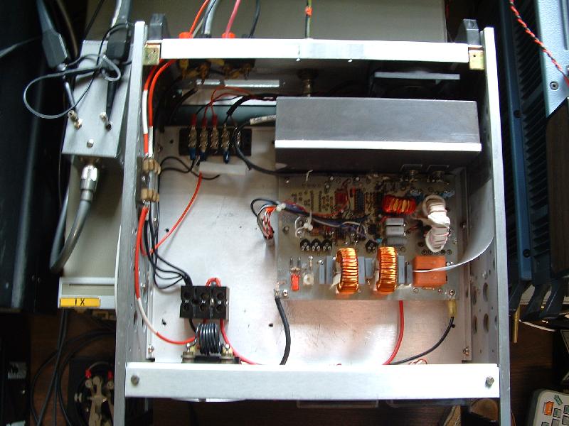
The amplifier is housed in a recycled telcom test set enclosure. The FETs are mounted on the fan cooled heat sink which turned out to be much larger than needed. While operating at about 86% efficiency very little heat is produced by the FETs. Some of the air from around the right side of the heat sink is channeled over the toroid cores by the Teflon sheet. The core temperature is held well within operating range by this air flow. The M0BMU "Scopematch" used for antenna tuning can be seen at the left rear of the amplifier. This has proven to be a very useful tool for antenna tuning and matching. With only 1 mw of RF input I have used this device up through 7 MHz.
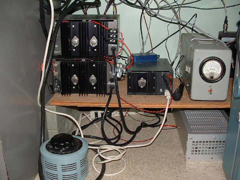
Power Supply
DC power for the amp is provided by two 20 amp Astron supplies. One supply is modified for floating ground. The unregulated DC from this supply is connected in series with the other supply's unregulated DC. A Variac autotransformer is used to adjust the amp output power by setting the FET voltage to around 36 volts for 400 watts output. A third 12 amp regulated supply provides 12 volt DC the the amp, the DDS exciter and a 386 MHz laptop computer used for keying the beacon ID.
Loading Coil
The antenna loading coil is fed through a toroid matching transformer made of 3 F-240-77 ferrite cores. I found this method on a GW4ALG web page. A one core transformer heated slightly but hardy no heat can be detected with 3 cores. A plastic cup is used for a rain shield.
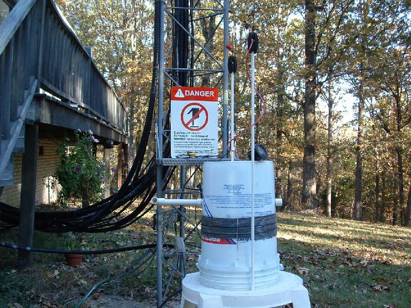
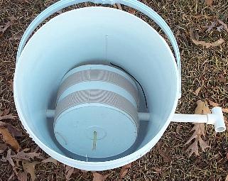
The "bucket" loading coil was originally used in the Part 15 band between 160 to 190 KHz. It has a variometer coil inside. The coil initially had about 2.5 mh of inductance but with a lot of top loading less than 1 mh is needed to tune the Part 5 antenna so a lot of wire has been removed

Variometer inside of bucket coil
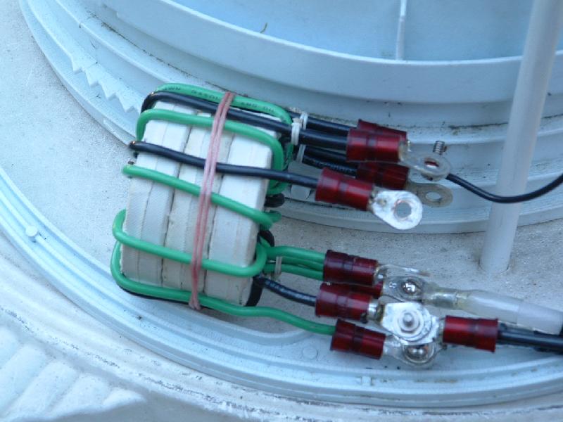
Matching Transformer
The coil matching transformer is wound on a stack of three F-240-77 ferrite cores. The primary is 10 turns of insulated solid #12 with a tap on turn 9 for fine tuning. The secondary has 8 turns of the same type wire with taps on turns 5, 6, 7 and 8. The antenna presently tunes perfectly by using 10 turns on the primary and 6 turns the secondary.
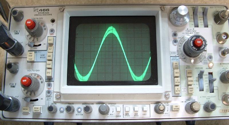
Antenna Tuning
Scopematch display showing antenna tuning and matching while running about 350 watts output. This display shows the antenna to be just slightly out of resonance. It also shows a slight impedance mismatch as the current is a little lower than the voltage. During normal operation the antenna is tuned for exact resonance and the matching transformer is adjusted for a perfect match.
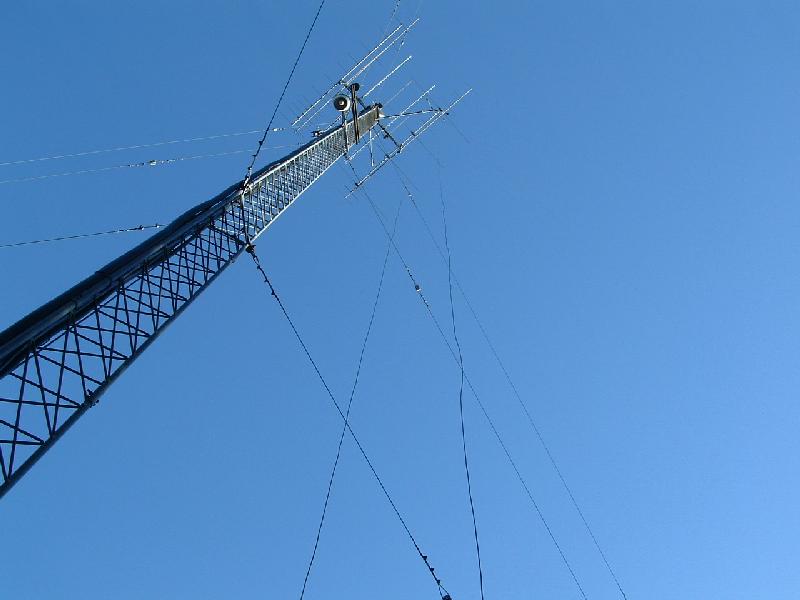
Antenna
The antenna is a grounded 100 foot tower with insulated guy wires. The tower is fed at the 95 foot level with a blanaced line spaced about 5 feet from the tower. I found this feed method on the ON7YD's 136 KHz Antenna Page. The US Patent No. for this design is: 3,984,839. (Click the patent number to view the patent) The top hat wires consists of what was a 160 meter dipole. A second wire was added to each leg and spread out to form "butterfly" type dipole elements. The ends of the elements on each side are joined.
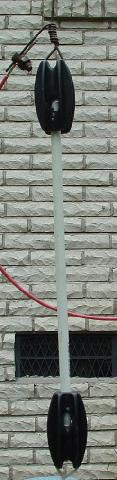
Antenna insulators consists of two electric fence plastic "egg" insulators connected by 12 inch sections of fiberglass electric fence post. A hole equal to the diameter of the fiberglass rod was drilled in one end of each egg insulator. The rod was inserted and pined with a small brass nail. This produced a strong lightweight high voltage insulator that was tested to hold 200 pounds.
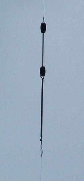
Insulator at about 60 feet above ground connected to a galvanized screen door spring and weed eater line. This holds one top hat wire to the top of an oak tree. A compound bow was used with a "Game Tracker" line attached to the arrow for rigging this top hat wire attachment and for getting other wires over the trees. I have been able to span up to 300 feet with this method.
Please advise me of errors or broken links in this page. Also if you have any suggestions which may help improve this installation.
![]()